Previous: Landing Gear |
| |
|
8/11-8/14/10 - Engine Install - 12 hrs
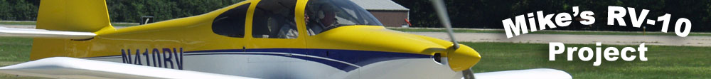
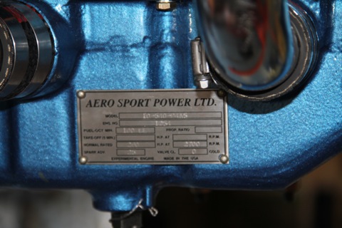
In July, right before our trip to Oshkosh, I got a delivery from AeroSport Power. I didn't have time to do anything other than confirm that it was indeed an engine. Well now we're back and it's time to get busy with engine stuff.
By the way, if you need an engine, you definitely should call Bart and Sue at AeroSport Power. This is my second engine from them. If this one performs anywhere close to the first one, I'll be a happy camper. |
 |
| |
|
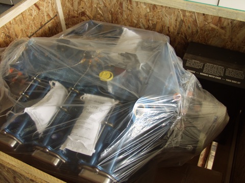
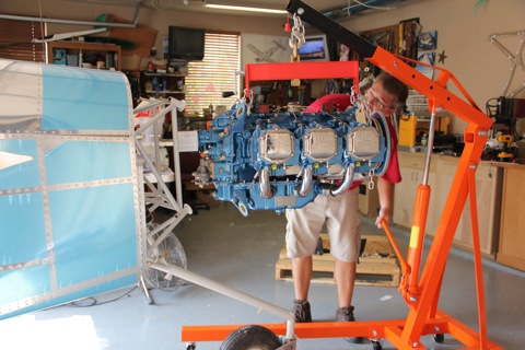
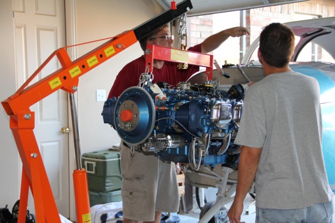
In order to get the engine up off the pallet and onto the engine mount, I needed a hoist. So I found a coupon for Harbor Freight and bought their one ton model. I think it ended up costing about $140 with the coupon and the addition of a load leveler.
Unfortunately, these things don't come assembled. So I ended up spending quite a while getting everything put together. |
 |
| |
|
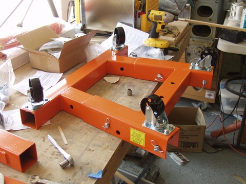
There it is in all its glory and ready to lift a 400 pound engine.
|
 |
| |
|
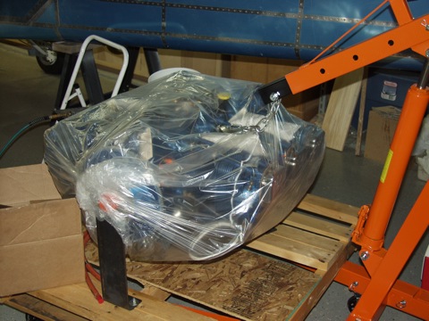
Next, I took apart the crate that was enclosing the engine so I could more easily pick the engine up. I eventually got the pallet up on the legs of the hoist, but it took some wrestling.
|
 |
| |
|
It took me a little while to figure out the load leveler and the chains, but I eventually determined that I needed a couple of bolts to connect the chain links together to form a loop at each end. After a few minutes of searching I had found some old hardware store bolts to do the trick.
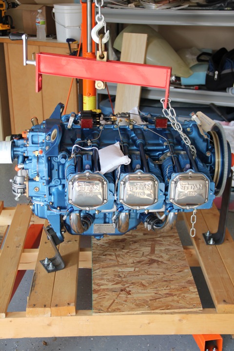
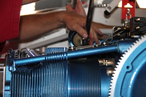
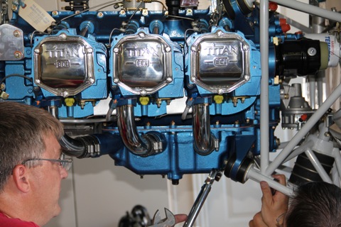
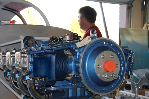
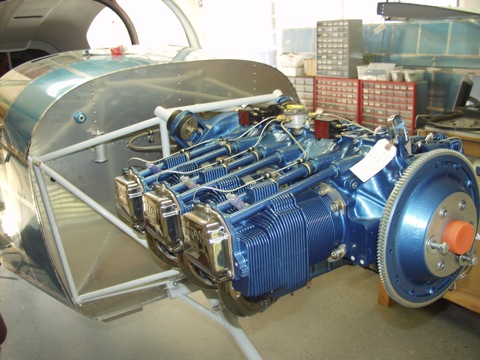
I took a few minutes to examine the engine. Boy, it's a beauty.
|
 |
| |
|
Man, it's hot this time of year in Texas. I looked at the thermometer and it was 106 degrees during the middle of the afternoon.
|
 |
| |
|
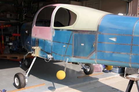
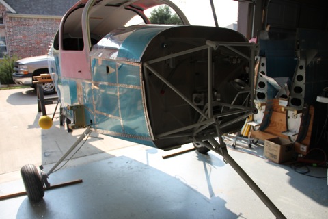
I also had to move the airplane so I had a spot where I could attach the engine more easily. To do that, I had to spend a while cleaning up the mess that I have made over the past few months. I had to remove some other items which were in the way, like my table saw.
I set some sawhorses outside and then backed the plane out of the garage until I had enough space to move the engine hoist around in front of the plane. |
 |
| |
|
The plane is still tail heavy at this point, so I had to build up the sawhorses with scrap wood until the nosewheel touched the ground.
|
 |
| |
|
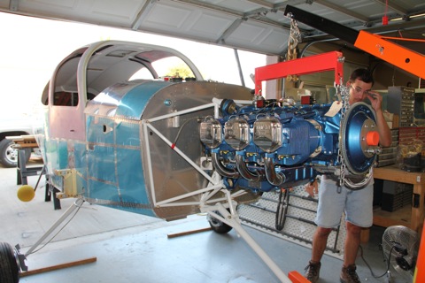
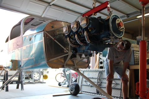
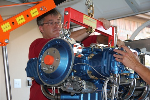
The engine was then hoisted up to be roughly in line with the engine mount. The hoist works like a champ.
|
 |
| |
|
It is at this point that I realized that Van's had sent me the incorrect dynafocal mounting hardware. The bag says EA DYNA BOLT, but apparently I should have received the one labeled EA DYNA BOLT I(O)540. The ones I received are for the other engines and are more than an inch longer than they need to be. I called Van's and they are sending me a new set, but they won't be here until next week.
So I called my friend, Todd, who isn't yet to this point and asked him if he had the correct bolts. He called me back later and he did indeed have the right bolts. So at least I can continue. Meanwhile I have some other things to attend to. |
 |
| |
|
There are several items on the instructions that need to be installed on the engine. So with the extra time I decided to go ahead and take care of these items. Mainly this involves replacing some fittings and/or setting the clocking of angled fittings.
|
 |
| |
|
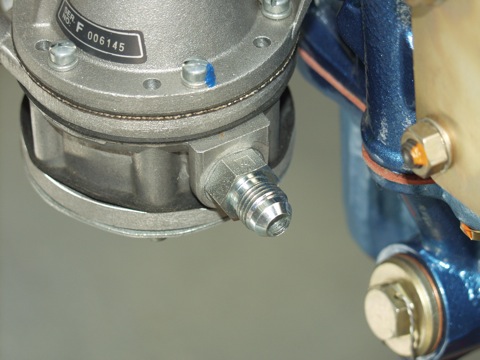
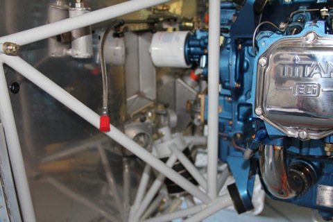
I put a straight fitting on the right side of engine driven fuel pump. The fuel line from the firewall is attached here.
|
 |
| |
|
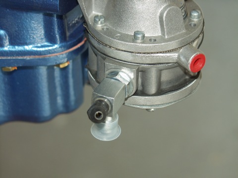
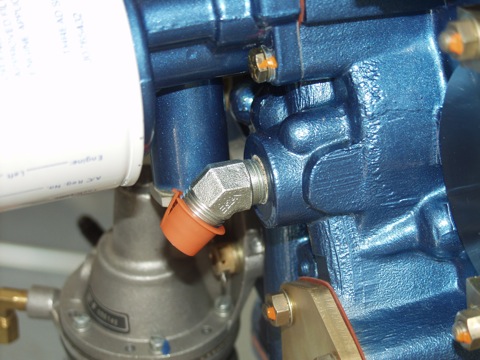
I put a right angle fitting on left side of engine driven fuel pump, which leads to the fuel injection system. Also you can see the restrictor fitting for the fuel pressure sensor.
|
 |
| |
|
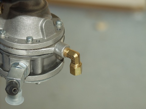
I then installed the brass right angle fitting for the fuel overflow tube.
|
 |
| |
|
I installed the first of the two oil fittings. This first one is on the top left of the accessory housing. I replaced the straight fitting that came on the engine with a 45 degree fitting as specified in the plans.
|
 |
| |
|
Next, I verified the second oil fitting, which was already on the engine. This one is on the right side. These two fittings will eventually have hoses that carry the hot oil to and from the oil cooler, which will be mounted on the firewall.
|
 |
| |
|
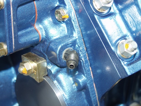
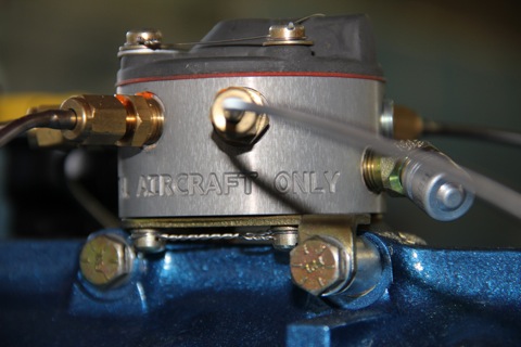
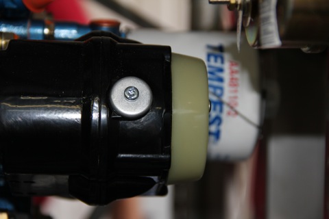
This is a restrictor fitting for the oil pressure sensor. It is on the right side of the accessory housing. A hose will eventually hook this up to the manifold, and an oil pressure sensor located on the firewall.
|
 |
| |
|
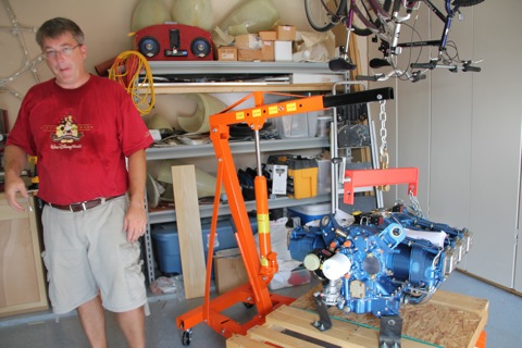
After work, Todd stopped by with the correct bolt kit, and he stayed around to help.
|
 |
| |
|
The reason I have so many pictures is because my lovely wife has a new camera and she loves to take pictures. So I asked if she would snap a few while I worked on the engine today. She took about 100 pictures, which is great for me because I would have maybe taken two.
|
 |
| |
|
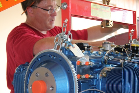
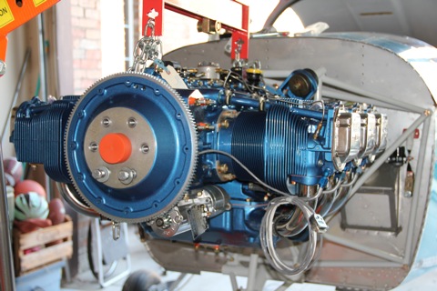
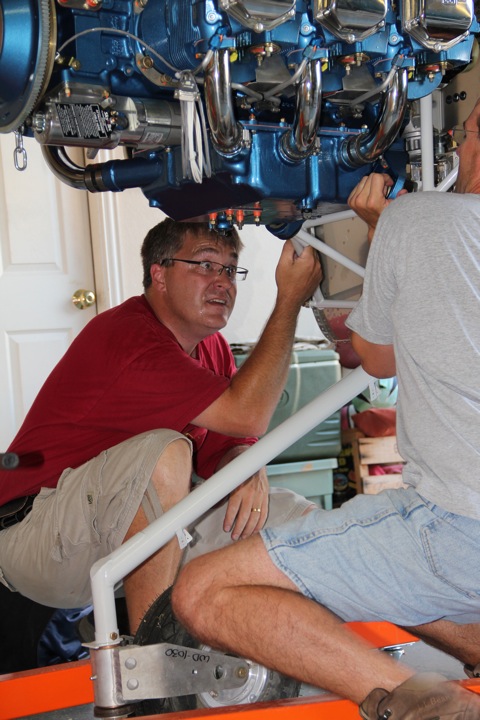
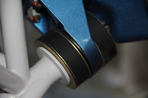
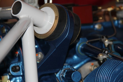
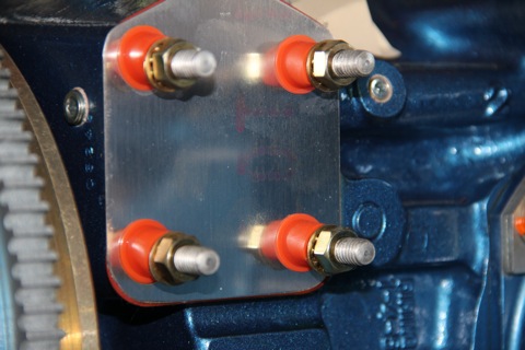
The engine is attached to the engine mount with four bolts. These bolts only line up properly when the engine is in the correct relationship with the airframe. Also, between the engine mount and the engine is a set of rubber vibration isolators. Some places call these "Engine Mounts" as well.
It takes a bit of coaxing to get the rubber engine mounts and the bolts to all be in their proper orientation with respect to the dynafocal mounting pads. |
 |
| |
|
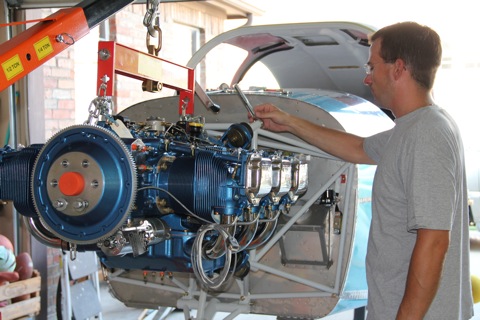
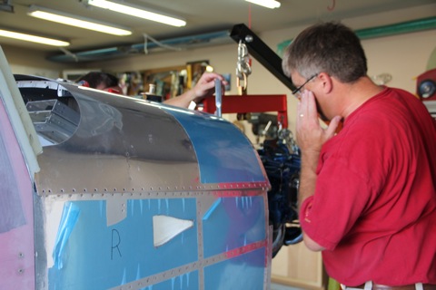
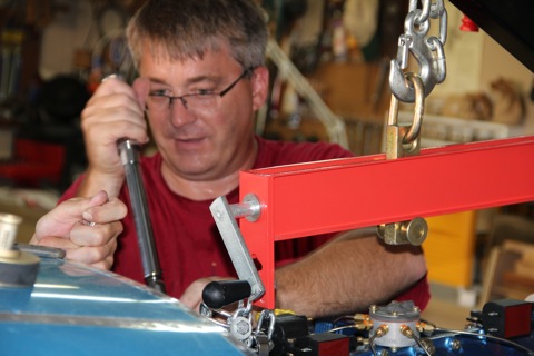
The load leveler is great for setting the "attitude" of the engine.
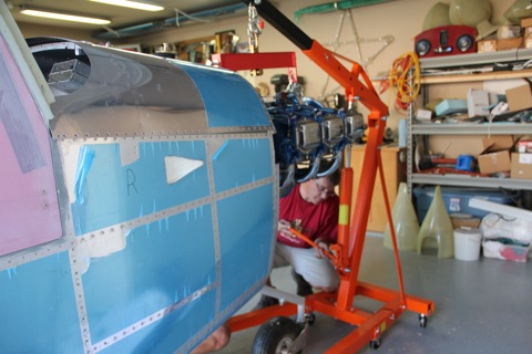
We ended up loosely installing the top bolts and then lifting and tilting the engine until the bottom bolts could be coaxed into position.
The bottom vibration mounts had to be installed at the same time as the bolt. You can't just insert the bolt and then add the rubber mount because the oil sump is in the way. So the bolt gets inserted part way and then the vibration mount is stuck in position and then the bolt is inserted the rest of the way. |
 |
| |
|
Let's see, lefty loosy...
|
 |
| |
|
| |
 |
| |
|
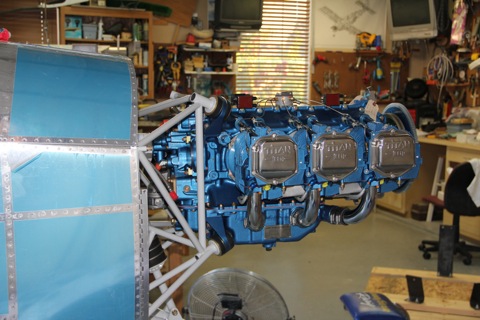
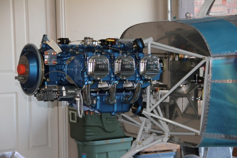
There is definitely a lot more space behind the engine than there was on the RV-9A. I think I might actually be able to remove the oil filter without becoming a contortionist.
|
 |
| |
|
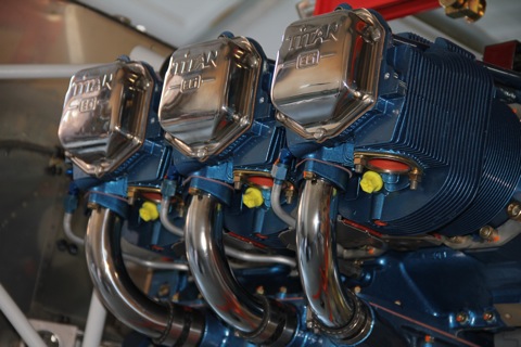
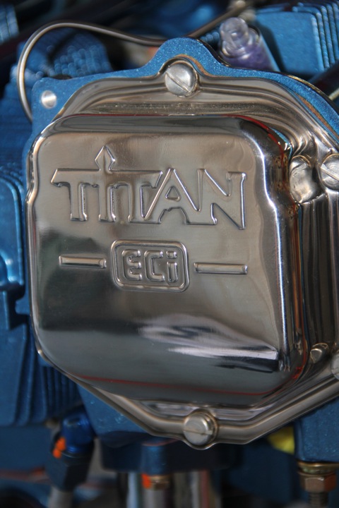
Oh, and I sprung for the chrome kit.
|
 |
| |
|
The roll of wire is for the direct crank sensor for the Lightspeed Plasma III electronic ignition. I have one mag firing the bottom set of plugs and one Lightspeed ignition firing the top set of plugs.
|
 |
| |
|
|
 |
| |
|
| |
 |
| |
|
| |
 |
| |
|
| |
 |
| |
|
| |
 |
| |
|
| |
 |
| |
|
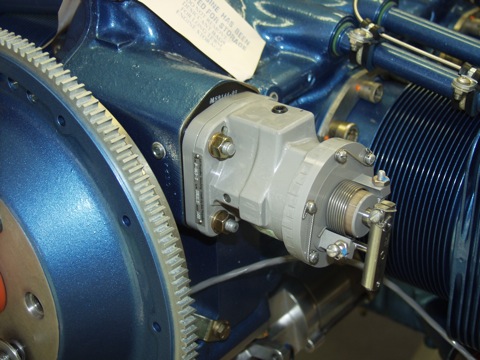
Here's where the prop governor will live...it's the governor's mansion!
|
 |
| |
|
| |
 |
| |
|
| |
 |
| |
|
I had to use a crow's foot to get to the bottom castle nuts.
|
 |
| |
|
| |
 |
| |
|
| |
 |
| |
|
| |
 |
| |
|
| |
 |
| |
|
| |
 |
| |
|
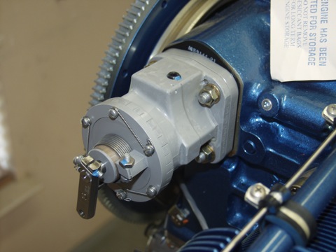
I installed the prop governor and quickly realized that the actuator arm isn't in the right place. So after a bit of searching I learned that I need to loosen the screws that are safety wired and then the front of the housing will rotate.
|
 |
| |
|
Currently the arm is at rest at the 6 o'clock position, and rotates to the 3 o'clock position. The control cable will extend upwards from the baffle. What I need is for it to be at rest at the nine or ten o'clock position and rotate to the six or seven o'clock position.
I'll do that later. Right now I'm just pumped to have the engine hanging on the plane!
|
 |
| |
|
Next: Misc. stuff
|
 |